35 Years Ago…
In 1986, Ivar Jacobson defined a use case for the first time. Today, 35 years later, this approach is still common! With the raise of the object-oriented programming the definition of use cases for a software becomes more and more relevant and popular. Using UML (Unified Modelling Language) without knowing about use cases and how to define them is unthinkable. Often the definition of all the different use cases of a software is one of the first steps when developing it[1].
Use Case Diagram
But what exactly is a use case? A use case describes single steps or sequences of events. Mostly a person is the centre of a use case and it can be used to describe their requirements. So, a use case always needs an actor and an action[1].
For example: The user wants to make calls with their smartphone. So, the user is the actor, to make a call is the action and the smartphone is the system, which is in the focus of the use case. Use cases are also part of UML and with this the scheme of use case diagrams are defined. They allow developer and designer of a software to create a graphical description of the requirements of their system[2]. For our example the use case diagram would look like this:
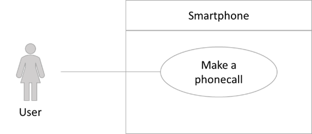
So, you can see, use case diagrams are relatively simple and clear. The actor is always represented as a figure and the action (or the “use case”) is described in an oval. The rectangle around the use case describes the context or the used system.
Use Cases of Flink2GO
In SPHERE we integrate and connect several tools and services for the construction sector within one platform. One of those tools is Flink2GO from Ascora. Flink2GO is a tool for faster defect detection of buildings during or after their construction process. It has many different functions and several target groups. One of its main features is the creation of tickets for detected defects. Such tickets are connected to a project/building and summarizes all information that are needed to fix the defect. This helps the craftsman as well as the architects and project managers. But all the functionality also makes the tool really complex and it is still in a process of development. So, more and more functionalities will be improved. However, also Flink2GO had some main use cases. But with every functionality and further development the number of use cases also increases.
When starting with the development and the creation process of a software one can define the different use cases the tool should cover. This will describe the requirements in a good and visual way. To improve the description even more, the written use cases can be transformed into use case diagrams. So, let’s have a look at some use cases of Flink2GO:
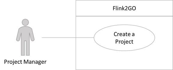
Within this tool there are four different roles – Normal, Craft Responsible, Project Manager, and Administrator. Normal, in this case, are craftsman or any other person without special rights to manage something in a project. As an example, when looking at the Project Manager, the following use cases can be defined:
A Project Manager is able to create a new project.
A Project Manager is able to create different buildings with multiple floors within his/her project.
A Project Manager can add building plans to the buildings of his/her project.
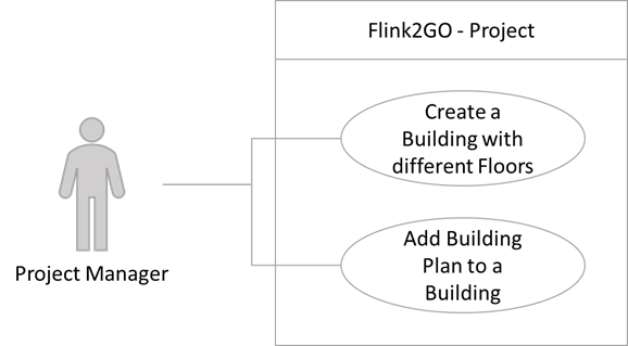
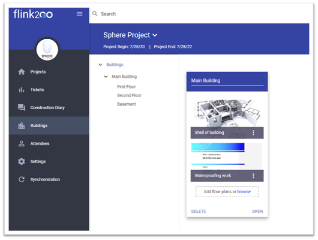
Of course, there are a lot more use cases for the Project Manager! This role has many rights and possibilities within this tool. But for demonstrating how it works, this should be enough. At first, we have described the use case in written form. So, it becomes clear which case the user wants to do in which context. After that, we created the diagrams for a better overview. When user and context are the same, we can summarize different use cases in one diagram. So, it becomes more clearer, where potential overlaps in the development will be. On the screenshot below, you can see how this use cases look in the final tool.
It is also possible to have more detailed use cases. The craftsman, for example, can create tickets when he/she detects a defect in the building and is not able to fix it right know. So, then it might be needed, that this defect will be documented and assigned to a person, who is responsible for that. The following use case results from this:
A Craftsman is able to create a ticket (within his/her project) with a title, information about location of the defect, needed craft, a description of the defect, a due date, internal and external responsible, and photos.
Especially for those more complex use cases it can be helpful to have a look on the diagram. Sometimes this can give a better overview.
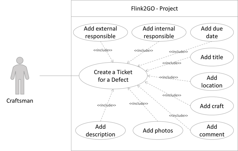
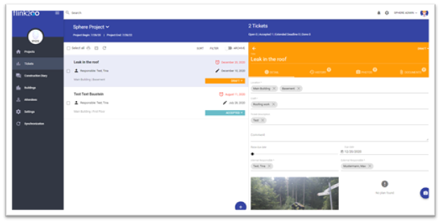
For this use case “create a ticket for a defect” there are several associations with a special relation to it. The “include” describes, that the other components, such as “add title”, are included in the linked use case. With these links we have the possibility to visualize also dependencies. Similar use cases are also defined for example “editing a ticket for a defect” and “show a ticket for a defect”. In the tool this use case looks like in the following screenshot:
Conclusion
To conclude, one can say that the definition of use case is a good possibility to describe requirements in a structured and clear way. The bigger the software is at the end, the more use cases one will have. For Flink2GO there will be probably several pages full of use cases. But especially for the beginning and for discussing requirements and potential features with stakeholders like customers, use cases and use case diagrams are a good tool, because they are easy to understand.
So, give it a try and describe the requirements for your next tool in use cases before starting the coding. Have fun and good luck with it!
Written by Carolin Wübbe, from Ascora
[1] Bittner, K., & Spence, I. (2003). Use Case Modeling. Addison-Wesley Professional.
[2]UML Use Case (18. 02 2021). UML diagrams.